Embedded One Blog
Battery Isolation
A brief history on the critical role of battery isolators.
Battery isolation is a crucial part of many electrical systems, especially those with multiple power sources. In this post, we will explore what battery isolation is, why it is important, and the different types of battery isolation methods.
Battery isolation is an important part of many electrical systems. It prevents unwanted current flow between batteries or power sources, allows for different batteries or power sources to be used for different purposes, and helps prevent safety hazards. There are several different types of battery isolation methods, each with its own advantages and disadvantages. Choosing the right method for your system will depend on your specific needs and requirements.
What Is Battery Isolation?
Battery isolation is the process of separating one battery or power source from another to prevent unwanted current flow. This is important in systems that use multiple batteries or power sources, such as boats, RVs, and off-grid homes. Without proper isolation, current can flow between batteries or power sources, which can cause damage or even create safety hazards.
Why Is Battery Isolation Important?
Battery isolation is important for several reasons. First, it prevents unwanted current flow between batteries or power sources, which can cause damage to the batteries or other components in the system. Second, it allows different batteries or power sources to be used for different purposes, such as starting an engine or powering appliances. Finally, battery isolation can help prevent safety hazards, such as electric shock or fire.
Types Of Battery Isolation
There are several different types of battery isolation methods, each with its own advantages and disadvantages. Some of the most common methods include:
Diode Isolation – Diodes can be used to prevent current flow between batteries. When a diode is placed in series with a battery, it allows current to flow in one direction only. This method is simple and effective but can result in a voltage drop and reduced efficiency.
Relay Isolation – Relays can be used to isolate batteries or power sources. When a relay is closed, it allows current to flow through the circuit. When it is open, current flow is stopped. This method is effective but requires a separate control circuit to operate the relay.
Solid-State Isolation – Solid-state switches, such as MOSFETs, can be used to isolate batteries or power sources. These switches are controlled by a voltage signal and allow for efficient switching. This method is effective but can be more expensive than other methods.
Low Side Drive
A brief background on low-side drives
Low side drive is a technique used in electronic circuits to switch a load on and off in high power applications. It is commonly used in motor control circuits and power management systems to control the flow of current to a load. In this blog post, we will explore what low side drive is, how it works, and its applications.
Low side drive is a technique used in electronic circuits to switch a load on and off in high power applications. It works by creating a voltage difference across the load to allow current flow. Low side drive is commonly used in motor control circuits and power management systems to control the flow of current to a load. It offers several advantages over high side drive, such as grounding the load and isolating it from the power supply. Understanding low side drive and its applications is crucial for anyone working with electronic circuits and power management systems.
What Is Low Side Drive?
Low side drive is a technique that allows the switching of a load on the negative side of a power supply. The load is connected between the negative side of the power supply and the output of the switching device. The switching device, usually a MOSFET or a transistor, is connected to the positive side of the power supply. When the switching device is turned on, current flows through the load and the device. When the device is turned off, the current flow stops, and the load is disconnected from the power supply.
How Does Low Side Drive Work?
Low side drive works by creating a voltage difference across the load to allow current flow. The voltage difference is created by the switching device, which acts as a gate to allow or block the current flow. When the device is turned on, the voltage difference is created, and current flows through the load. When the device is turned off, the voltage difference disappears, and the load is disconnected from the power supply.
Applications Of Low Side Drive
Low side drive is commonly used in motor control circuits, where it is used to control the speed and direction of a motor. It is also used in power management systems to switch power to a load, such as a light or a heating element. Low side drive is preferred over high side drive in some applications because it allows the load to be grounded and isolated from the power supply.
High Side Drive
A brief background on high-side drives
High side drive is a technique used in electronic circuits to switch a load on and off in high power applications. It is commonly used in motor control circuits and power management systems to control the flow of current to a load. In this blog post, we will explore what high side drive is, how it works, and its applications.
What Is High Side Drive?
High side drive is a technique that allows the switching of a load on the positive side of a power supply. The load is connected between the positive side of the power supply and the output of the switching device. The switching device, usually a MOSFET or a transistor, is connected to the negative side of the power supply. When the switching device is turned on, current flows through the load and the device. When the device is turned off, the current flow stops, and the load is disconnected from the power supply.
How Does High Side Drive Work?
High side drive works by creating a voltage difference across the load to allow current flow. The voltage difference is created by the switching device, which acts as a gate to allow or block the current flow. When the device is turned on, the voltage difference is created, and current flows through the load. When the device is turned off, the voltage difference disappears, and the load is disconnected from the power supply.
Applications Of High Side Drive
High side drive is commonly used in motor control circuits, where it is used to control the speed and direction of a motor. It is also used in power management systems to switch power to a load, such as a light or a heating element. High side drive is preferred over low side drive in some applications because it allows the load to be grounded and isolated from the power supply.
Conclusion
High side drive is a technique used in electronic circuits to switch a load on and off in high power applications. It works by creating a voltage difference across the load to allow current flow. High side drive is commonly used in motor control circuits and power management systems to control the flow of current to a load. It offers several advantages over low side drive, such as grounding the load and isolating it from the power supply. Understanding high side drive and its applications is crucial for anyone working with electronic circuits and power management systems.
State of Health (SOH)
SOH methodological overview
Battery state of health (SOH) is an important metric in battery management that describes the overall condition and performance of a battery over time. SOH refers to the ability of a battery to store and deliver energy compared to its original capacity when it was new. In this article, we will explore what SOH is, how it is measured, and its importance in battery management.
What Is State Of Health?
State of health (SOH) is a measure of the overall condition and performance of a battery over time. SOH is expressed as a percentage of the battery’s original capacity. For example, a battery with an SOH of 80% has 80% of its original capacity remaining.
Measuring SOH
There are several methods for measuring SOH, including:
Capacity Testing: Capacity testing is a method of measuring SOH by discharging the battery and measuring the amount of energy that it can deliver. The results of the test are compared to the battery’s original capacity to determine its SOH.
Impedance Testing: Impedance testing is a method of measuring SOH by measuring the internal resistance of the battery. As a battery ages, its internal resistance increases, which can be used to estimate its SOH.
Voltage Testing: Voltage testing is a method of measuring SOH by measuring the voltage of the battery at rest. As a battery ages, its voltage decreases, which can be used to estimate its SOH.
Importance Of SOH
SOH is an important metric in battery management because it provides valuable information about the overall health and performance of a battery. Monitoring SOH over time can help identify when a battery is nearing the end of its useful life and needs to be replaced. SOH can also be used to optimize the use of the battery by determining the appropriate charge and discharge rates, as well as the appropriate depth of discharge.
In addition, maintaining a battery’s SOH within a safe and optimal range can help prevent safety hazards, such as overcharging or over-discharging, which can lead to reduced battery life, decreased performance, and even safety hazards.
Conclusion
Battery state of health (SOH) is a measure of the overall condition and performance of a battery over time. SOH can be measured using capacity testing, impedance testing, or voltage testing. Monitoring SOH over time is important for identifying when a battery is nearing the end of its useful life and for optimizing the use of the battery. Maintaining a battery’s SOH within a safe and optimal range is crucial for ensuring the longevity and performance of the battery. Understanding SOH and its importance is critical for anyone working with batteries or battery-powered systems.
State of Charge (SOC)
SOC methodological overview
Battery state of charge (SOC) is an important aspect of battery management in many applications, from electric vehicles to renewable energy systems. SOC refers to the amount of energy stored in a battery as a percentage of its total capacity. In this article, we will explore what SOC is, how it is measured, and its importance in battery management.
What Is State Of Charge?
State of charge (SOC) is a measure of the amount of energy stored in a battery. It is expressed as a percentage of the battery’s total capacity. For example, a battery with a SOC of 50% has half of its total energy storage capacity available.
Measuring SOC
There are several methods for measuring SOC, including:
Coulomb Counting: Coulomb counting is a method of measuring SOC by tracking the amount of charge that flows in and out of the battery. This method is based on the principle that the SOC is equal to the integral of the current over time.
Open Circuit Voltage (OCV): OCV is a method of measuring SOC by measuring the voltage of a battery when it is not connected to any load or charger. The voltage of a battery is directly related to its SOC, and a battery’s voltage can be used to estimate its SOC.
Internal Resistance: The internal resistance of a battery increases as the SOC decreases. By measuring the internal resistance of a battery, it is possible to estimate its SOC.
Importance Of SOC
SOC is an important aspect of battery management in many applications. In electric vehicles, for example, SOC is used to estimate the remaining range of the vehicle and to determine when to charge the battery. In renewable energy systems, SOC is used to determine the amount of energy that can be stored and used during periods of low energy production.
Overcharging or over-discharging a battery can lead to reduced battery life, decreased performance, and even safety hazards. Maintaining the SOC within a safe and optimal range is critical to ensuring the longevity and performance of the battery.
Conclusion
Battery state of charge (SOC) is a measure of the amount of energy stored in a battery as a percentage of its total capacity. SOC can be measured using coulomb counting, open circuit voltage, or internal resistance. SOC is an important aspect of battery management in many applications, from electric vehicles to renewable energy systems. Understanding SOC and its importance is crucial for anyone working with batteries or battery-powered systems.
UART
UART Protocol Overview
Universal Asynchronous Receiver/Transmitter (UART) is a type of serial communication protocol commonly used in microcontrollers, embedded systems, and other electronic devices. In this article, we will explore what a UART is, how it works, and its applications.
What Is UART?
UART is a communication protocol that enables two devices to communicate with each other serially. It is a simple, cost-effective, and widely used method of transmitting data between devices. UART is often used to communicate with peripherals such as sensors, displays, and other devices in embedded systems.
How Does UART Work?
UART uses two data lines, namely the TX (transmit) line and the RX (receive) line, to transfer data between devices. The TX line is used to transmit data from the transmitting device, while the RX line is used to receive data at the receiving device.
UART communication involves a start bit, data bits, an optional parity bit, and a stop bit. The start bit is always a logic low (0) signal, and it signals the receiving device that data is coming. The data bits represent the actual data being transmitted and can range from 5 to 9 bits. The parity bit is an optional bit used for error detection, while the stop bit is always a logic high (1) signal and indicates the end of a data packet.
UART communication is asynchronous, meaning that the transmitting device and receiving device do not share a common clock signal. Instead, the receiving device synchronizes to the start bit of each data packet and uses the timing of the data bits to determine the bit rate and data content.
Applications Of UART
UART is widely used in many electronic devices and systems, including:
Microcontrollers: UART is often used to communicate between a microcontroller and other devices, such as sensors or displays.
Personal Computers: UART is used to communicate between the computer and devices, such as modems, printers, and GPS receivers.
Industrial Control Systems: UART is used in industrial control systems to communicate between devices, such as programmable logic controllers (PLCs) and sensors.
Embedded Systems: UART is used in embedded systems to communicate between devices, such as microcontrollers, displays, and sensors.
Conclusion
UART is a widely used communication protocol that enables two devices to communicate with each other serially. It is a simple and cost-effective method of transmitting data between devices and is commonly used in microcontrollers, personal computers, industrial control systems, and embedded systems. Understanding how UART works and its applications is important for anyone working with electronic devices and systems.
What is a Battery Management System?
BMS Overview
As the use of battery-powered devices becomes more widespread, the importance of battery management systems (BMS) cannot be overstated. A battery management system is a critical component in the design of any battery-powered device, from electric vehicles to portable electronic devices. In this article, we will explore what a battery management system is, its components, and its importance in battery-powered devices.
What Is A Battery Management System?
A battery management system is an electronic system that monitors and controls the charging and discharging of a battery pack. Its main purpose is to ensure the safe and efficient operation of the battery, as well as to extend its lifespan. The BMS accomplishes this by regulating the voltage and current levels during charging and discharging, preventing overcharging, and monitoring the state of the battery.
Components Of A Battery Management System
A typical battery management system consists of several components, including:
Battery Charger: The battery charger is responsible for charging the battery pack. It is designed to provide a constant voltage or current to the battery to ensure that it charges safely and efficiently.
Battery Monitor: The battery monitor measures the voltage, current, temperature, and state of charge of the battery. It provides real-time information about the battery's condition to the BMS, which then uses this information to regulate the charging and discharging of the battery.
Cell Balancer: The cell balancer is responsible for ensuring that each cell in the battery pack is charged and discharged evenly. It accomplishes this by monitoring the voltage of each cell and diverting current from the cells that are fully charged to those that need more charging.
Battery Protection Circuit: The battery protection circuit protects the battery from overcharging, over-discharging, and short-circuiting. It is designed to disconnect the battery from the device if any of these conditions occur, preventing damage to the battery and the device.
Importance Of Battery Management Systems
Battery management systems are critical to the safe and efficient operation of battery-powered devices. Without a BMS, the battery can be overcharged or over-discharged, which can lead to reduced battery life or even battery failure. In addition, without a BMS, the battery may not be charged evenly, leading to differences in the capacity of the cells and reducing the overall performance of the battery pack.
In summary, a battery management system is a critical component in the design of any battery-powered device. It ensures the safe and efficient operation of the battery, extends its lifespan, and maximizes its performance.
What is Bluetooth Low Energy?
Bluetooth Low Energy Overview
What Is Bluetooth Low Energy - An Overview
BLE stands for Bluetooth Low Energy. It is a form of wireless communication designed especially for short-range communication. BLE is very similar to Wi-Fi in the sense that it allows devices to communicate with each other. However, BLE is meant for situations where battery life is preferred over high data transfer speeds.
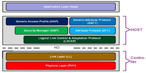
Layers Of BLE
BLE is organized in a number of layers. Each layer has its purpose and plays a significant role in making a BLE device function properly. There are three building blocks of BLE.
Application Layer
Host Layer
Controller Layer
The Application: Is the highest layer and the one responsible for containing the logic, user interface, and data handling of everything related to the actual use-case that the application implements. The architecture of an application highly depends on the project developed with BLE.
The Host: Consists of the following layers
Generic Access Profile (GAP)
Generic Attribute Profile (GATT)
Logical Link Control and Adaptation Protocol (L2CAP)
Attribute Protocol (ATT)
Security Manager (SM)
Host Controller Interface (HCI), Host side
The Controller: Includes the following layers
Host Controller Interface (HCI), Controller side
Link Layer (LL)
Physical Layer (PHY)
Figure 2: BLE Protocol Stack
Characteristics In Bluetooth Low Energy
Characteristics are containers for user data. They always include at least two attributes: the characteristic declaration (which provides metadata about the actual user data) and the characteristic value (which is a full attribute that contains the user data in its value field).
Additionally, the characteristic value can be followed by descriptors, which further expand on the metadata contained in the characteristic declaration. The declaration, value, and any descriptors together form the characteristic definition, which is the bundle of attributes that make up a single characteristic.
The characteristic declaration attribute’s type UUID (0x2803) is a standardized, unique UUID used exclusively to denote the beginning of characteristics. As with all other declarations (such as service and include), this attribute has read-only permissions, because clients are allowed only to retrieve its value but in no case modify it.
Throughout Difference Between BLE 4 And BLE 5
Speed:
Bluetooth 5 is faster than Bluetooth 4 with the former having 2Mbps, twice the speed of the Bluetooth 4 of about 1Mbps making the Bluetooth 5 able to meet one of IoT requirements. This is thanks to the 5Mbps bandwidth of the Bluetooth 5 in comparison to 2.1Mbps of the Bluetooth 4.
Range:
Bluetooth 4 supports 50m in outdoor range and 10m in indoor range making it so low whilst Bluetooth 5 supports 200m in Line-of-Sight path in outdoor environment and 40m in indoor environment. Therefore, if someone wants to listen to music with wireless headsets while moving around the house or the courtyard, then the Bluetooth 5 will work best.
Power Requirement:
The Bluetooth 5 has been formulated to use less power on your device compared to the Bluetooth 4. That means you can keep your Bluetooth switched on for a longer period of time and do much more compared to Bluetooth 4 which consumes more power than its newer counterpart.
Message Capacity:
The Bluetooth 4 has a small message capacity of about 31bytes which gives just 17 to 20 bytes for actual data payload while the Bluetooth 5 with a large capacity of 255bytes gives more bytes for actual data payload.
Bluetooth Beacon:
With Bluetooth 5, beacons have become more popular due to the speed and range increase while with Bluetooth 4, they are less popular due to the less speed and range as well as low message capacity of 31bytes.
Support For IoT Devices:
Bluetooth 5 easily meets the requirements for IoT devices with its good range and increase in speed while Bluetooth 4 does not due to its low speed and short working range. That means IoT devices will work well with Bluetooth 5 and utilize all its features properly, for example the new Samsung Galaxy 8 and Galaxy 8+.
Compatibility:
Bluetooth 4 works best with devices that are compatible with version 4 series but will not work with devices that have Bluetooth 5 while Bluetooth 5 is backward compatible with v1, v2, v3, v4, v4.1 and version 4.2 but will not utilize all the features of Bluetooth 5.
Mesh Networking In BLE 4 And Added Feature In BLE 5
BLE 4 was introduced in 2010 and it did not have capability of mesh networking. It was capable of connecting with only one device at a time. Mesh networking was introduced back in 2017. Mesh networking was 1st added in BLE 5. BLE 5 mesh networking allows many-to-many (m:m) device communication and is optimal for the creation of networks on a large scale. It is ideal for environmental monitoring, automation asset tracking and IoT devices that require thousands of devices to communicate simultaneously.
Practical Uses Of Bluetooth Low Energy 5
With its low power consumption, inexpensive hardware, and small form factors, BLE5 provides scope for a wide range of applications. In previous iterations, Bluetooth Low Energy technology was largely used for storage, beacons, and other low-power devices, but came with some serious limitations. For instance, wireless headphones were unable to exchange messages under BLE4.
With Bluetooth 5.0, all audio devices can share data via Bluetooth Classic, and Bluetooth Low Energy is now more applicable for wearable devices, smart IoT devices, fitness monitoring equipment, and battery-powered accessories such as wireless keyboards.
What is Controller Area Network (CAN)?
CAN Overview
What Is Controller Area Network?
CAN (Controller Area Network) is a real-time control technology Protocol uses two-wire differential serial communication. The CAN Bus Protocol was 1st created for the automotive industry to connect transmissions, airbags, antilock braking/ABS, cruise control, electric power steering, audio systems, power windows, doors, mirror adjustment, battery, and recharging systems for hybrid/electric vehicles, among other things.
CAN-BUS Hardware Layer
The Physical Layer is the basic hardware required for a CAN network, i.e., the ISO 11898 electrical specifications. It converts 1’s and 0’s into electrical pulses leaving a node, then back again for a CAN message entering a node. Although the other layers may be implemented in software or in hardware as a chip function, the Physical Layer is always implemented in hardware.
There are several different physical layers:
The most common type is the one defined by the CAN standard, part ISO 11898-2, and it’s a two-wire balanced signaling scheme. It is also sometimes known as “high-speed CAN”.
SAE J2411 defines a single-wire (plus ground, of course) physical layer. It’s used chiefly in cars – e.g., GM-LAN.
Several proprietary physical layers do exist.
Modifications of RS485 were used in the Old Ages when CAN drivers didn’t exist.
Go to Section 5 to view a number of oscilloscope pictures for those interested in the details of a message.
Two Wire System
CAN bus uses two dedicated wires for communication. The wires are called CAN high and CAN low. The CAN controller is connected to all the components on the network via these two wires. Each network node has a unique identifier. All ECUs on the bus are effectively in parallel and that’s why all the nodes see all of the data, all of the time. A node only responds when it detects its own identifier. Individual nodes can be removed from the network without affecting the other nodes.
When the CAN bus is in idle mode, both lines carry 2.5V. When data bits are being transmitted, the CAN high line goes to 3.75V and the CAN low drops to 1.25V, thereby generating a 2.5V differential between the lines: each of the CAN lines is referenced to the other one, not to vehicle ground. Since communication relies on a voltage differential between the two bus lines, the CAN bus is NOT sensitive to inductive spikes, electrical fields or other noise. This makes CAN bus a reliable choice for networked communications on mobile equipment.

CAN Bus Termination
Terminal resistors are needed in CAN bus systems because CAN communication flows are two-way. The termination at each end absorbs the CAN signal energy, ensuring that this is not reflected from the cable ends. Such reflections would cause interference and potentially damaged signals.
The reflection challenge grows with the length of the cables as well as the CAN bus bit rate. This is why it is critical to add proper termination in larger CAN networks. There are two types of terminations, Standard termination and Split Termination, Termination can lead to communication issues if not done properly.
Arbitration
CAN is a peer-to-peer network, there is no master to control the transmission between nodes. When a node in CAN is ready to transmit data, it usually undergoes through a process called message arbitration. In the message arbitration process, CAN node will check to see if the bus is idle and initiates the transmission once the bus is idle. This action triggers the other CAN nodes in the bus and results in two or more nodes starting a message at a same time which results in a conflict in the network. It can be resolved by following methods,
Transmitting node checks the bus while they are sending data
If any node in the network detects a dominant level (logical 0) when sending a recessive level itself, it will fail in the arbitration process and quits immediately will start acting as a receiver.
This arbitration process is performed while sending the arbitration ID field of the CAN frame and at the end, only one transmitter is left on the bus i.e., the node with the highest priority (lowest arbitration ID) will pass the arbitration.
After that, the node which has won the arbitration will continue message transmission as if nothing had happened.
Difference Between CAN 2.0 And CAN FD
CAN 2.0CAN FDData bit rate is max 1 MbpsMax data bit rate is 8 MbpsA maximum of 8 bytes of data can be sent in one frame without Transport Protocol64 bytes of data can be sent in one frame without the TP layer.Multiple CAN nodes can broadcast message frames.Only one node transmits at a time; one of the reasons for increased bit rateNo BRS or FDF to switch the speed to higher or lower levelsBit Rate Switch (BRS), Flexible Data Rate Format (FDF) and Error State Indicator (ESI) together ensure higher speed.Cyclic Redundancy Code contains a 15bit codeCRC field has 17 or 21 check codesLess secured due to less data payload capacity
Enhanced security of data as CAN FD data can be encrypted using the extra memory
DLC, Message ID And Data Byte Payload
Data Length Code. A part of the CAN message. It used to mean simply the length of the CAN message, in bytes, and so had a value between 0 and 8 inclusive. In the revised CAN standard (from 2003) it can take any value between 0 and 15 inclusive, however the length of the controller area network message is still limited to at most 8 bytes. All existing CAN controllers will handle a DLC larger than 8.
Data byte Payload is a serialized request structure. Up to 8 bytes of data can be transmitted through a single CAN Bus message. DLC field, or Data Length Code.
CAN Bus Message Protocol
The CAN communication protocol is a carrier-sense, multiple-access protocol with collision detection and arbitration on message priority (CSMA/CD+AMP). CSMA means that each node on a bus must wait for a prescribed period of inactivity before attempting to send a message. CD+AMP means that collisions are resolved through a bit-wise arbitration, based on a preprogrammed priority of each message in the identifier field of a message.
The higher priority identifier always wins bus access. That is, the last logic high in the identifier keeps on transmitting because it is the highest priority. Since every node on a bus takes part in writing every bit “as it is being written,” an arbitrating node knows if it placed the logic-high bit on the bus.

Figure 1: CAN Bus Message Protocol
Structure Of Controller Area Network Frame:
SOF: SOF stands for the start of frame, which indicates that the new frame is entered in a network. It is of 1 bit.
Identifier: A standard data format defined under the CAN 2.0 A specification uses an 11-bit message identifier for arbitration. Basically, this message identifier sets the priority of the data frame.
RTR: RTR stands for Remote Transmission Request, which defines the frame type, whether it is a data frame or a remote frame. It is of 1-bit.
Control field: It has user-defined functions.
IDE: An IDE bit in a control field stands for identifier extension. A dominant IDE bit defines the 11-bit standard identifier, whereas recessive IDE bit defines the 29-bit extended identifier.
DLC: DLC stands for Data Length Code, which defines the data length in a data field. It is of 4 bits.
Data field: The data field can contain up to 8 bytes.
CRC field: The data frame also contains a cyclic redundancy check field of 15 bit, which is used to detect the corruption if it occurs during the transmission time. The sender will compute the CRC before sending the data frame, and the receiver also computes the CRC and then compares the computed CRC with the CRC received from the sender. If the CRC does not match, then the receiver will generate the error.
ACK field: This is the receiver’s acknowledgment. In other protocols, a separate packet for an acknowledgment is sent after receiving all the packets, but in case of controller area network protocol, no separate packet is sent for an acknowledgment.
EOF: EOF stands for end of frame. It contains 7 consecutive recessive bits known End of frame